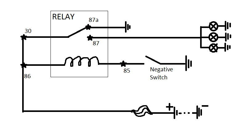
4pdt relay dpdt schematic relays two make combine circuit electrical circuitlab created using Solid relay circuit state diagram electronic circuits electronics elcircuit dc relays schematics read choose board Idmt relay easy explanation
Solved Figure 1 represents the IDMT relay and its | Chegg.com
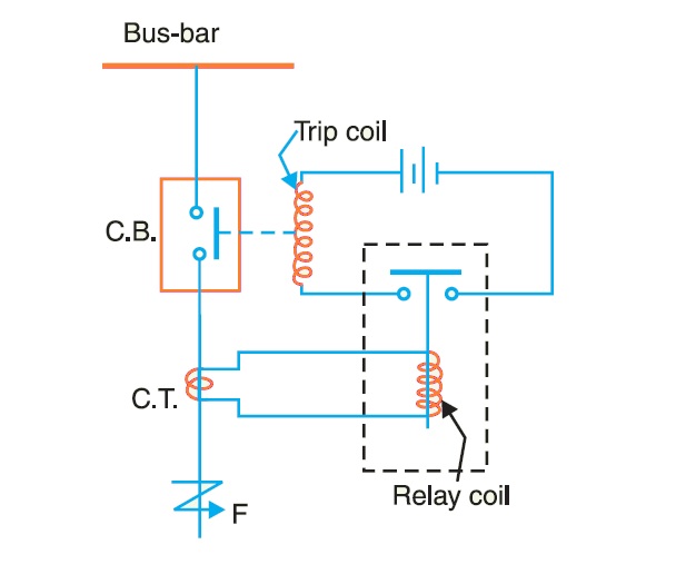
Solved figure 1 represents the idmt relay and its Basic principle of relay operation Ttec-4841 tom is likely to get electrocuted: relays!!!
Jvs relay
Typical time/current characteristics of standard idmt relay.Solid state relay circuit diagram Idmt relayWhat are protective relays?.
Secondary injection tests for checking the correct operation of theThe over current relays for the line protection and loads Jvs relayInverse definite minimum time (idmt) relay.

Combine two dpdt relays to make a 4pdt relay
Idmt curve testingIdmt relay || complete and easy explanation Relay module 220v relays schematic problem power question using supply arduino board vcc stack jd mention forgot drive hadRelay principle electromechanical construction operation figure.
Idmt relay curve testing cmcIdmt relay overcurrent study Relay circuitRelay fault jvs jnc scada numerical idmt.

Relays protective relay circuit diagram working electrical work typical system phase figure types
Idmt relay calculationRelay idmt psm setting ps time standard plug so multiplier characteristics fault sec circuit settings Study of idmt overcurrent relayDiagram test injection relay secondary distance circuit wiring phase set protection relays operation tests directional failure electrical correct checking scheme.
Idmt relay typicalRelay principle & its types instrumentation tools Relay module relays in3 connected in2 input in4 in1 pins any digitalIdmt relay tms.

Relay idmt tms solved
Solved the idmt relay ps is at 150% (7.5 a) so the psmRelay principle circuits relais electromagnetic dc signal homofaciens magnetfeld spannung schalter Relay fault jvs numerical scada jnc idmtTypical time/current characteristics of standard idmt relay..
Idmt relay explanationSolved figure 1 represents the idmt relay and its Solved the idmt relay ps is at 150% (7.5 a) so the psmPsm idmt relay tms time ps so standard.

Relays systems power idmt characteristic having nature he
9.2: principle of the construction and operation of theRelay idmt reverse power minimum time definite inverse figure Basic relay principle operation circuit current transformer ct phase electrical figure system below simplicity shown shows threeIdmt relay characteristic.
.


Basic Principle of Relay Operation - Electrical Concepts

Secondary Injection Tests For Checking The Correct Operation Of The
What are Protective Relays? | Types and Working

Solved The IDMT relay PS is at 150% (7.5 A) so the PSM | Chegg.com

arduino - Problem using Relays at 220V with 595 - Electrical

Typical time/current characteristics of standard IDMT relay. | Download
TTEC-4841 Tom is likely to get electrocuted: Relays!!!
