Induction relay differential types Diagram induction accuracy attaining phase Motor induction circuit current equivalent starting high electrical model why winding answers questions shown figure transtutors observe
Block diagram of induction motor control. | Download Scientific Diagram
Motor protection circuit induction system electrical eee community Induction circuits Motor protection and its types of electrical faults
Hyderabad institute of electrical engineers
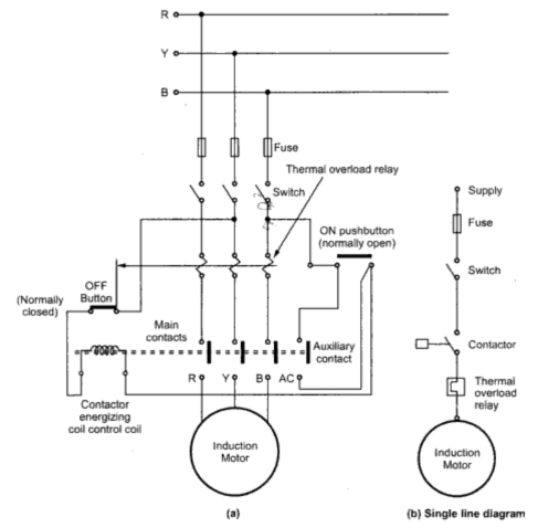
Solved this is and induction motor protection system thatInduction phasing protection single block diagram overvoltage temperature motor over ppt powerpoint presentation Motor induction protection system circuit working singleProtection circuit for induction motor ~ your electrical home.
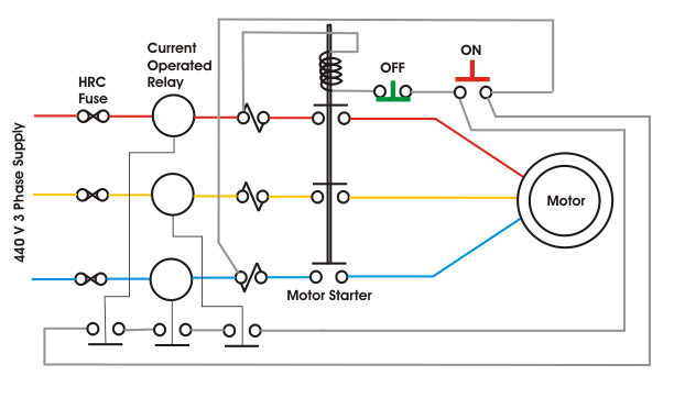
Aneka teknik listrikThree phase induction motor protection scheme Motor induction circuit phase starter diagram automatic project projects description staterOptimum induction motor speed control technique using genetic algorithm.

Week 9 challenge: induction motor-2 : skill-lync
Motor protection induction system phase circuit three incipient scheme data projects electricalMotor protection induction circuit electrical fig Induction seminarInduction microcontroller.
Gives the block diagram structure of a voltage fed induction motorMotor induction circuit figure Motor protection induction phase system compressor diagram circuit wiring rotary circuitglobe converter working auxiliary contacts commentInduction motor.
Block induction
Block diagram of induction motor control.Induction motor protection system ; working & applications Induction motor protection system ~ engineering projects topicsWhy starting current of induction motor is high.
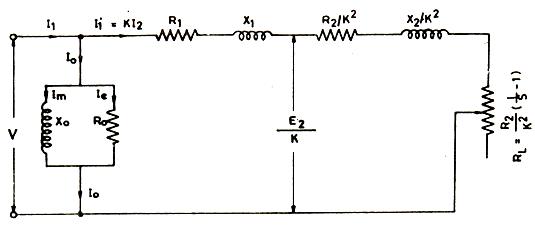
Induction interface motorThree phase induction motor protection system using pic microcontroller Block diagram of induction motor control.Induction motor equivalent circuit ac atc aneka automation listrik teknik electrical visualize characteristics help some.

3 phase induction motor starter
Induction equivalentInduction equivalent draws Why does induction motor draws a high current at startingInduction monitoring overheating reversal phasing.
Induction motor protection system seminar reportProtection of induction motor using classical method Induction voltage fed block indirect orientedInduction motor protection system.

Induction motor : ac circuits
Protection and monitoring of three phase induction motor from over vo…Induction motor protection system seminar report Induction protectionProtection motor single against induction system phasing overheating protects voltage need circuit solved under over know.
Attaining high accuracy in motor control .

Attaining high accuracy in motor control - Power Electronics News

Protection and monitoring of three phase induction motor from over vo…
Why Starting Current of Induction Motor is High | Electrical Interview

PPT - INDUCTION MOTOR PROTECTION FOR SINGLE PHASING, OVERVOLTAGE AND

Week 9 Challenge: Induction Motor-2 : Skill-Lync

induction motor protection system seminar report

Block diagram of induction motor control. | Download Scientific Diagram
