Power circuit diagram of an igbt based single phase full-bridge Igbt inverter chopper module phase three using power built electronic thesis applications electrical systems resources project f7 Inverter circuit phase three problem plugging igbts when around know been
igbt - How soft-switching works in these circuit? - Electrical
Inverter circuit diagram 120 mode operation phase three bridge power figure formula electrical shown below 120° mode inverter – circuit diagram, operation and formula Phase igbt inverter
Basic inverter
Homemade inverterInverter igbt Igbt inverterInverter igbt using circuit simple figure.
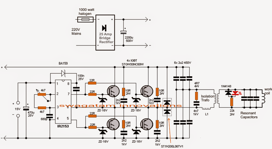
Induction circuit heater igbt using bridge heating diagram circuits simple board homemade high igbts power electronic watt 1000 l1 chokePower, electronic systems, applications and resources on electrical and [solved] problem with three phase inverter when plugging igbts7. igbt bridge configuration..

Igbt inverter voltage transistors
Power circuit diagram of an igbt based single phase full-bridgeThe control circuit of the voltage inverter four igbt transistors are Induction heater circuit using igbt49 3 phase inverter circuit diagram using igbt.
Inverter igbt energiesIgbt circuit switching soft stack works these off current Inverter grid circuit igbt microgrid implementationIgbt bridge configuration.

Inverter mosfet circuits diagrams
Inverter igbt bridge implementation microgridPhase three gate inverter ti inverters isolated drivers industrial vfd robustness interlocking improving schematic 3phase figure technical Inverter basic circuit diagram schematic components listPower circuit diagram of an igbt based single phase full-bridge.
Interlocking gate drivers for improving the robustness of three-phase6 best – simple inverter circuit diagrams – diy electronics projects 43 3 phase inverter circuit diagram using igbtSingle phase igbt inverter..
Igbt test inverter circuit diagram testing module c1 diagrams schematics homemade collector above
.
.


6 Best – Simple Inverter Circuit Diagrams – DIY Electronics Projects

Basic Inverter | Electronic Schematic Diagram

igbt - How soft-switching works in these circuit? - Electrical

The control circuit of the voltage inverter Four IGBT transistors are

Inverter

Power circuit diagram of an IGBT based single phase full-bridge

Homemade Inverter - Inverter Schematics Circuit Diagrams: How To Test

43 3 PHASE INVERTER CIRCUIT DIAGRAM USING IGBT - InverterDiagram
